Digital Modes Meanderings
The Antenna System Particulars
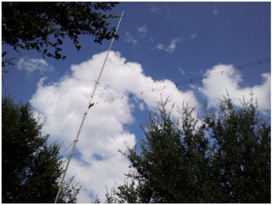
The antenna is a vertical doublet 37 feet in height and is constructed from 1.25 inch diameter aluminum tubing. The tubing length of 37 feet is an arbitrary number dictated by the availability of tubing on hand. The entire length on hand was utilized to help the radiation resistance stay as high as possible on the 40 and 30 meter bands where the doublet is less than a half wavelength. This in turn helps to keep the radiation efficiency high on those bands as well. The tubing diameter aids in the rigidness of the antenna as a structure and is beneficial in reducing the ohmic losses of the radiating element. The individual pieces of tubing are swaged on one end and slip fit together to get a total length of 18.5 feet for each half of the radiating element. Each overlapping piece is coated with an anti-oxidant conductive compound before assembly to prevent aluminum corrosion and facilitate conductivity of the connection. The two halves of the radiating element are joined together with a piece of 1.50 inch diameter PVC tubing that is 2 feet in length. Each half of the radiating element is centered and secured into the PVC tubing with about 1 inch of space between the ends of the two pieces of aluminum tubing. The PVC tubing provides a method of joining the two halves of the radiator as well as providing an insulator for the feed point.

Anti-oxidant compound >>
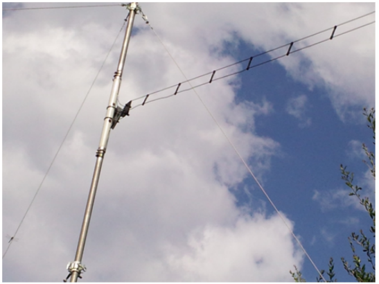
A non-metallic plate is centrally mounted on the center insulator to provide an attachment point for the feed line. The two individual wires of the open wire feed line are each routed directly to one half of the doublet radiator. The wires are soldered to the center of a rectangular piece of thin copper sheet 3” x 4” in dimension. The backsides of these copper sheets are coated with an anti-oxidant conductive compound to prevent dissimilar metal (aluminum / copper) oxidation and facilitate conductivity of the connection.
The copper sheets are attached to the tubing just past the ends of the PVC center insulator. They are wrapped around the aluminum tubing and held in place with two stainless steel hose clamps. This comprises the feed point of the doublet.
The vertical doublet
The copper sheets are attached to the tubing just past the ends of the PVC center insulator. They are wrapped around the aluminum tubing and held in place with two stainless steel hose clamps. This comprises the feed point of the doublet.
The vertical doublet
|
Notice that there are no coils, matching networks, traps or anything that can be detrimental to the overall efficiency of the radiator. Even mechanical connections have been minimized in both the feed line and the radiator itself. There is nothing but highly conductive materials.
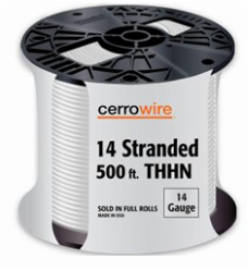
Type of wire used for OWL >> |
|
The feed line is made from THHN 14 gauge stranded copper wire separated by spreaders 3.75 inches wide. These dimensions equate to about 580 ohms surge impedance for the open wire line. The exact numerical value of the feed line impedance is not very important. The more important specification is the matched line loss figure of .104 dB per 100 feet at 28 MHz. It goes without saying that all frequencies below 28 MHz have an even lower loss value. If at 28 MHz the SWR on the feed line was 10:1 the total feed line loss would be .25 dB for 100 feet of feed line. At 20:1 SWR the total feed line loss would be only 1.0 dB for 100 feet of feed line. For all intents and purposes the feed line can be essentially viewed as “lossless” for the high frequency (HF) spectrum.
Close up of the feed point insulator
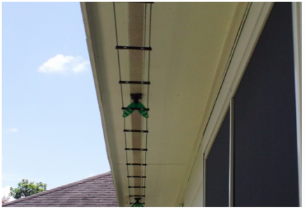
The component that makes it possible to utilize all the benefits of a tuned feeder antenna system is the antenna tuner. Without this vital piece of equipment we could not enjoy the low loss, high efficiency, frequency independent operation we get from using a tuned feeder system. While the choice of using an antenna tuner is not an option, the choice of what kind of tuner is an option. The two options are a balanced line tuner or an unbalanced line tuner. There are advantages and disadvantages to both. I chose to use an unbalanced line antenna tuner. By choosing an unbalanced line tuner another choice was made by default. You cannot just connect a balanced feed line to an unbalanced line tuner. You need to convert the balanced feed line to an unbalanced feed line (e.g. coax cable). A balanced to unbalanced transformer does just that, hence the name balun. A balun is always used in conjunction with an unbalanced antenna tuner when used with open wire line feeders. The balun used is a 1:1 current type balun which was designed for operating with a tuned feeder antenna system. An additional reason to use a current balun is to help force the feed line to have equal currents in each conductor. This helps to keep the line from radiating due to feed line imbalance.
|
|
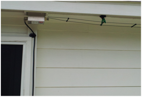
Feed line under the house eaves Balun feed line transition