The Common Mode Filter / Balun Project 2014
Built by AB5V, Randy Friesenhahn
Recently I was discussing RF noise on the bands and how at times it was really bad at my QTH. I live near Magnolia TX and this far out even though I live in a neighborhood there should not be this much noise on the HF bands. Usually at night things quiet down but during the summer and usually most daylight hours this noise gets pretty loud. It causes the DX stations on 20, 17, 15, 12 and 10 to be voices in the noise. On Quiet days/nights its Okay they are just week but we can make a contact. Ed N5EM and Rick W5RH and I have discussed this at time and both have recommended an article from the National Contest Journal* Titled “Excellent, Easy, Cheap Common-Mode Chokes” Written by Chuck Counselman.
Its not on line right now but the original longer and more detailed article is posed at Yankee Clipper Contest Club
See this link: Common-Mode Chokes by Chuck Counselman, W1HIS
To summarize Chuck goes on in his article how to build a very reliable system of chokes to reduce common mode noise on the HF bands. The build calls for each choke to be constructed out of RG-142 Teflon Coax and four Fair-Rite Cable Bead p/n # 2631102002. (These are available from Mouser Electronic and usually in stock under the same part number )
I added to this at this point but this section is up to you. One source of potential noise is the balanced to unbalanced transition between the coax and the dipole. I have made small 1:1 Baluns before and they worked well but this is ONLY to be used with TUNED resonant antennas period. Do NOT tune through a balun.
I built 1:1 Baluns out of T-200-2 Toriods from the Toriod King.com he has a great selection and these units are tested (BY ME) to work from 3.5 to well over 30 MHz. The loss on 160 meters was too great and for that band no 1:1 was used my station runs 600 to 1KW out and with 3.5 dB loss in the Balun that’s a lot of heat and is asking for trouble. I will be researching this and hope to install one at some point in the future. I need to find a better mix of toriod material that will work better below 4 MHz.
I built and tested the baluns and what I learned was pretty interesting. The construction took longer that I thought it would and for good reason.
I built and tested the baluns and what I learned was pretty interesting. The construction took longer that I thought it would and for good reason.
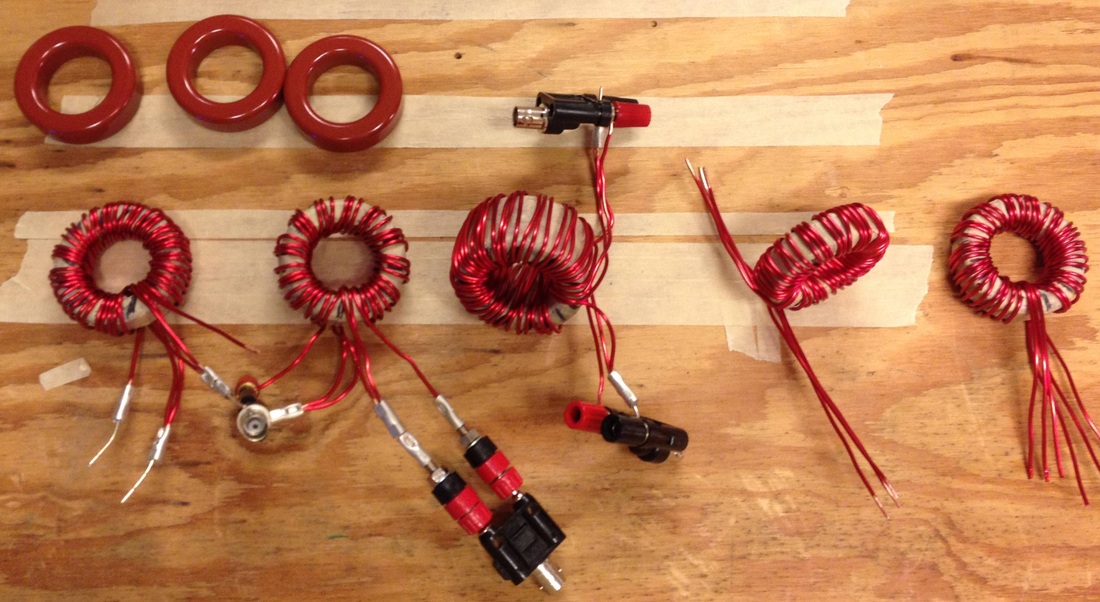
First a T-200-2 toriod core is big but delicate you can crack and chip them take your time. Next 14 AWG solid Magnet wire is tough stuff to wind! Okay its not to bad to wide but to make this balun look nice it can be pretty hard. I found out that you get better with practice (go figure!) Next I tested each balun to see what worked best on which band, surprisingly you could hook them up and measure right through them with out issues on the HF bands as you got closer to 3.5 MHz the losses became bad however and at 1.8 Mhz they were too high to be acceptable. Even on 80M (3.5 MHz) the losses were not to good I consulted with Ed N5EM and he suggested that I try to add more windings or get a bigger toriod. Bigger cores were not immediately available so I tried more windings. The balun schematic I was using called for 13 trifler windings so I went up to 15 and eventually 17. These cores tested great on 7.0 MHz but not on 3.5 MHz. These was nearly 3.2 dB of loss but almost none on 7.0 Mhz. Okay I thought how about stacking two cores? So I stacked two T-200-2 cores and taped them up. Note I used common masking tape I should have used fiberglass tape but I had always used it on smaller things in the past without issue. It turned out later the masking tape was acceptable. Finally I wound a 16 turn Balun on the dual core assemble. It was big and heavy but when tested… The loss dropped to a measure loss of 2.5 dB at 3.5 MHz acceptable for 80M! Unfortunately loss of 160 was still slightly above 3 dB So the decision was made to go a choke only for the 160 Meter band.
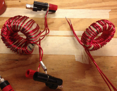
Completed Baluns Ready for testing.
Next I started building the common-mode chokes, much easier. I pulled four cores from the box (I ordered enough to build two full sets or 20 choke sets !) I went and got some RG-142 and started to cut coax sets. Note here the reason the author used RG-142 is that coax is rated at 3.5KW at HF frequencies. At standard amateur power levels it can handle just about anything but its expensive! I have seen it priced up to $5.00 a foot. I used surplus coax I had but do NOT use cheap coax if you plan to run more than 200 Watts period. Excellent alternatives are LMR-240, rated at 2.0 KW it is physically similar and would be Okay for most users, it is about the same as RG-8X but its dual shielded very important. Another smaller coax is RFC-195 a dual shielded UHF coax about like RG-58 rated at 1.9 KW at HF its about $0.70 a foot and is commonly used for WiFi antennas. These will work but be careful if you run big power you REALLY need the RG-142 or the LMR-240.
Constructions starts with cutting the coax to about 28 “ and then threading the coax through two side by side cores three times. With RG-142 that’s all you can get through there. Then move down NO less than 12 to 14 inches. According to Mr. Councilman if you go less you can easily get unwanted coupling and defeat the choke. Now assemble the second set of chokes just like the first. Finally use a zip tie on each end to lock each pair of cores tightly together as shown in the illustrations and you’re done with this unit.
Constructions starts with cutting the coax to about 28 “ and then threading the coax through two side by side cores three times. With RG-142 that’s all you can get through there. Then move down NO less than 12 to 14 inches. According to Mr. Councilman if you go less you can easily get unwanted coupling and defeat the choke. Now assemble the second set of chokes just like the first. Finally use a zip tie on each end to lock each pair of cores tightly together as shown in the illustrations and you’re done with this unit.
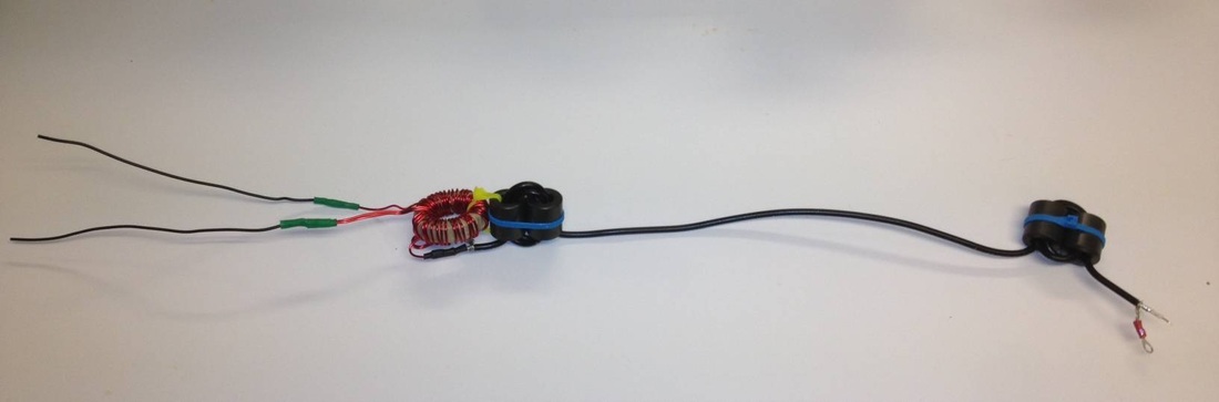
You have to build one for in the station at each transceiver and then one for each antenna. I use dipoles only right now so the ends of my chokes have wire coming out of the PVC pipes they are housed in. If you’re going to a yagi that has a balanced feed you can use this other wise skip the balun and install two SO-239 connectors. I realized the assemblies were BIG and they would need large PVC pipe of protest them from the weather.
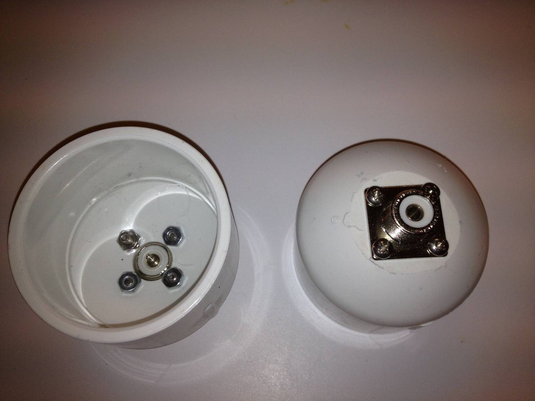
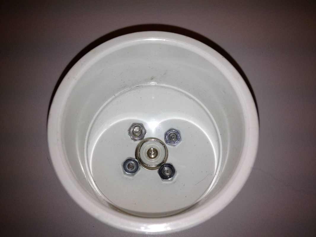
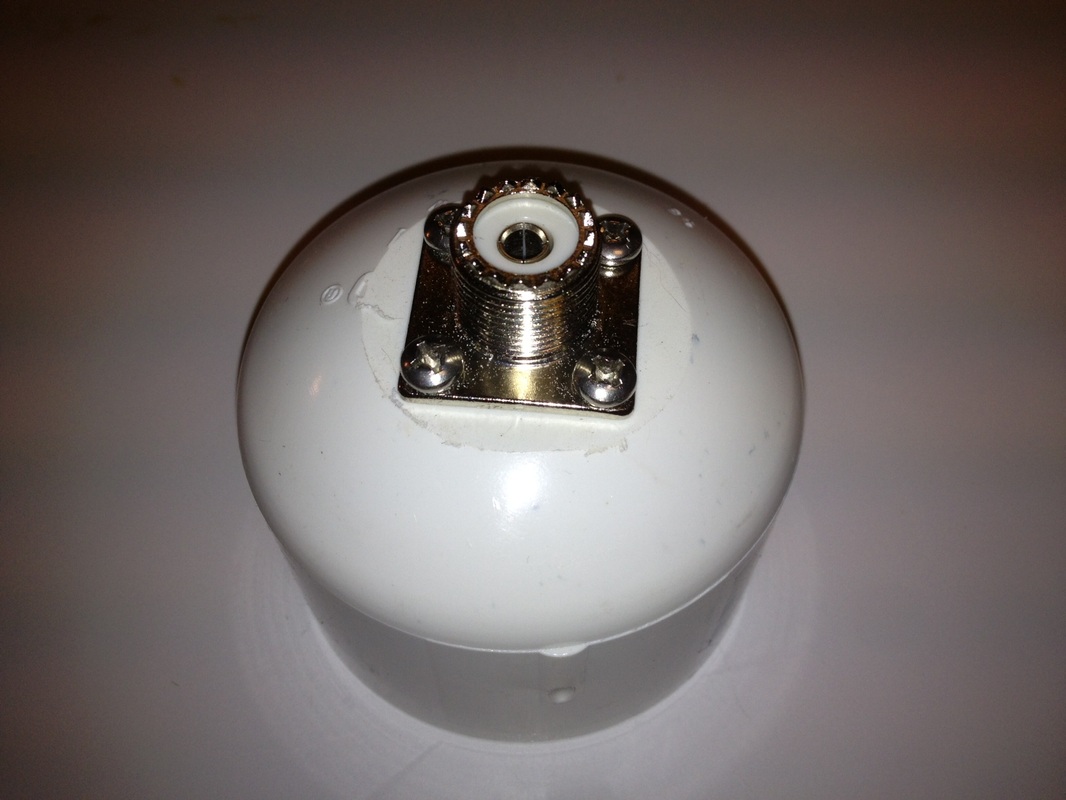
The antennas have to stay up long periods in all of the terrible Texas heat and rain storms we get here in South East Texas I used Schedule 80 PVC pipe from the “big orange box” store and caps for the ends. At the bottom I ground the cap so the SO-239 would sit flush. I then used a step bit to drill holes for the bottom of the SO-239 and a smaller bit to accommodate the 6-32 screws that would hold it in place. The screws, washer, and nuts were ALL stainless to be sure they would last a long time.
The antennas have to stay up long periods in all of the terrible Texas heat and rain storms we get here in South East Texas I used Schedule 80 PVC pipe from the “big orange box” store and caps for the ends. At the bottom I ground the cap so the SO-239 would sit flush. I then used a step bit to drill holes for the bottom of the SO-239 and a smaller bit to accommodate the 6-32 screws that would hold it in place. The screws, washer, and nuts were ALL stainless to be sure they would last a long time.
On the other end I encountered an issue. The balun was too large to fit in the PVC pipe so I added a 2” PVC coupler. I added a 2” PVC nipple to go to the top cap. I assembled the coupler and nipple waited a few hours for them to set then drilled them for the side eyebolts and the wires to the dipole. The top cap was drilled for the eyebolt that would be used to support the choke/balun assembly.
Choke/Balun assembly in housing
Next I primed all the surfaces and prepared for finial assembly. I attached the lower end to the bottom cap with the SO-239 and applied the PVC cement. I installed the screw- or shield of a PL-259 to the bottom SO-239 to protect it for the next step. I slid the cap on applying as much force as possible to get it to seat well, I put my weight on it against the work bench and the cap seated well.
Now the second set of cores should be just below the end of the PVC pipe carefully attach the balun using heat shrink tubing to protect the wires better from each other. Then attach the top wires to the dipole as shown.
Now apply the cement to the inside of the top section. (Note I am not a plumber and I learned it’s a LOT neater to put the cement inside the fittings and not on the tubing.) . Now bend the wires into a gentle bends (about 90 degrees or ¼ of a circle) and feed them through the wire holes below the side eyebolts. Make sure the PL-259 shield is on the SO239 and push down on the top assembly while pulling on the wires this stretches out the choke insuring the 12” minimum spacing is maintained. The finial step is to use a white urethane construction sealant (or urethane calking) to seal the wire holes. Now the assembly needs to dry for a few hours to make sure the wires and PVC have properly set.
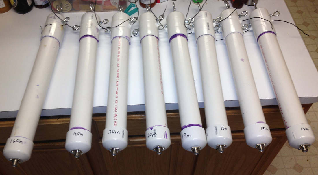
Assembled Balun/Choke assemblies ready to install on the Antennas
Measured performance
During high noise periods on 80 meters the measure steady noise was S9 + 10 peak with an average of about S8 to S9. I installed a newer dipole near the original antenna and tuned it with the choke. SWR was easily adjusted and the two were compared over the next few days. Immediately it was noticed that what had been a steady S9 noise level dropped on the test antenna to slightly over S7. Receiver noise measure with a HP-400C AC voltmeter the noise both broad spectrum and above 1500 Hz was measure at 9 to 10 dB. Receiver tests were great with no detectable signal loss on signals in the 80 meter band. Stations in the DX Window were clear and now above the noise on the test antenna and I successfully worked England one evening, not bad.
Results on 40 meters were similar with noise averaging S7 to S8 dropping to below S5 and DX station much clearer on 40 and the system was successful. I am hoping to report additional success as I go up the bands with new antennas for each band up to 10 Meters.
At this point I am not sure 100% how much I have improved things but I have not hurt station performance
More on this project as I install the rest of the chokes and the newer dipoles.
73
AB5V
Randy Friesenhahn
Parts List:
Description Quantity Manufacturer Part Number
1) RF Cable Bead 4 Fair-Rite Cable Bead p/n # 2631102002
2) T-200-2 toriod 1 Toriod King Part number T-200-2
3) Teflon Double Shield Coax 28" Beldon RG-142
4) 2" PVC Pipe 18"
5) 2" Double Female PVC pipe coupler 1
6) 2" PVC End Caps 2
7) Female Coax Connector 1 SO-239
8) 14 AWG Wire 12"
9) 14 AWG Coated magnet Wire 70"
10) 1/4" x 3" Zink plated Eye bolts 3
11) 1/4" Zink plated NY-Lock Nuts 6
12) 1/4" Zink Plated Lock Washers 6
13) 6-32 x 3/4" Stainless machine screws 4
14) 6-32 x 3/4" Stainless nuts 4
15) 6-32 x 3/4" Stainless lock washers 4
16) PVC Primer and Cement kit 1
Thanks to Ed manual N5EM and Rick Hiller W5RH for your advice and ideas during this project.
Footnotes:
Note* National Contest Journal January / February 2013
“Excellent, Easy, Cheap Common-Mode Chokes”
by Chuck Councelman
Note** American Radio Relay League
Amateur Radio Handbook 1980
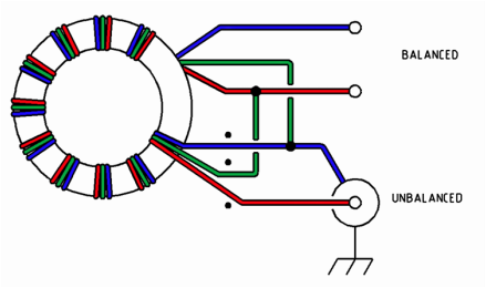
1:1 Balun construction
During high noise periods on 80 meters the measure steady noise was S9 + 10 peak with an average of about S8 to S9. I installed a newer dipole near the original antenna and tuned it with the choke. SWR was easily adjusted and the two were compared over the next few days. Immediately it was noticed that what had been a steady S9 noise level dropped on the test antenna to slightly over S7. Receiver noise measure with a HP-400C AC voltmeter the noise both broad spectrum and above 1500 Hz was measure at 9 to 10 dB. Receiver tests were great with no detectable signal loss on signals in the 80 meter band. Stations in the DX Window were clear and now above the noise on the test antenna and I successfully worked England one evening, not bad.
Results on 40 meters were similar with noise averaging S7 to S8 dropping to below S5 and DX station much clearer on 40 and the system was successful. I am hoping to report additional success as I go up the bands with new antennas for each band up to 10 Meters.
At this point I am not sure 100% how much I have improved things but I have not hurt station performance
More on this project as I install the rest of the chokes and the newer dipoles.
73
AB5V
Randy Friesenhahn
Parts List:
Description Quantity Manufacturer Part Number
1) RF Cable Bead 4 Fair-Rite Cable Bead p/n # 2631102002
2) T-200-2 toriod 1 Toriod King Part number T-200-2
3) Teflon Double Shield Coax 28" Beldon RG-142
4) 2" PVC Pipe 18"
5) 2" Double Female PVC pipe coupler 1
6) 2" PVC End Caps 2
7) Female Coax Connector 1 SO-239
8) 14 AWG Wire 12"
9) 14 AWG Coated magnet Wire 70"
10) 1/4" x 3" Zink plated Eye bolts 3
11) 1/4" Zink plated NY-Lock Nuts 6
12) 1/4" Zink Plated Lock Washers 6
13) 6-32 x 3/4" Stainless machine screws 4
14) 6-32 x 3/4" Stainless nuts 4
15) 6-32 x 3/4" Stainless lock washers 4
16) PVC Primer and Cement kit 1
Thanks to Ed manual N5EM and Rick Hiller W5RH for your advice and ideas during this project.
Footnotes:
Note* National Contest Journal January / February 2013
“Excellent, Easy, Cheap Common-Mode Chokes”
by Chuck Councelman
Note** American Radio Relay League
Amateur Radio Handbook 1980
1:1 Balun construction